Friday, November 20, 2020

Racing against the Sunset: Shifting the Process to Reaching Deadlines


This past week I spent creating these merged and complete models, then realizing there are slight imperfections, or areas that I know I can improve, I went back to take more photos and improve on those areas. I have two of the models completed out of the set of six, while six was the arbitrary goal set at the beginning and is flexible, I am determined to finish the other four this coming weekend in order to meet the December 1st deadline for the conference.

                A recording of my 15-minute PowerPoint presentation on the project is due on the first of December for the Society for Historical Archaeology (SHA) conference . I am willing to condense the number of models I will create down from six if need be but I intend to try and meet this initial goal. This implies I finish the rest of the models and accept the small imperfects in each model instead of the slight tweaking I have been doing this past week. I can always go back and tweak them more after the December 1st deadline or mention them in the limitations of the project.  The goal besides creating these models is to then print them and compare them in relation to the low-cost methods I am using.

                I adapted some of my methods over the past week and learned more about the capabilities of Metashape, which continues to surprise me the more I use it. A limitation last week was the processing time for each model, and I decided that due to approaching deadlines, I turned the detail down from “High” to “Medium” which processes in about 5 minutes as opposed to an hour which helped me save a lot of time working on this project. This does mean, however, that the quality of the overall model is lower albeit more than acceptable.  I additionally found that the arrow heads have a unique problem with alignment as the automatic alignment of the different chunks does not really work for these sharp and flat pieces. I learned how to manually align these chunks which is a little more time intensive but was the last step to creating the finish model and overall, was not too difficult.

                I am surprised by the quality of these 3D models since the photos themselves were taken on my phone, which is apart of the low-cost of the project, and I have realized over the course of this project that it is the quality of the input that most drastically affects the output. The greatest impact on these models is the number of photos collected in each profile; the lower the amount of photos the worse and blurrier the final result, while the higher the amount of photos collected results in a crisp high definition model. Incomplete, or missing, sections of certain models already send me back to restart the process again which is only made worse if I rush the picture process as the low resolution sends me back to do it again and correctly. This project has taught me to do my due diligence when taking the first step in the modelling process as building off of a poor photo collection is like building on a shaky foundation, it does not matter how much effort I put in after that point because it will only cause my efforts to be less than ideal.

This is one of the completed models. What was the lower half before the merging process had less photos in its profile and resulted in a blurry product. Once merged together with the higher resolution upper half, this creates a slightly jarring result. I am unsure if this will translate through the resin 3D printing process.


Update: Considering this is the last blog for this internship for the Fall 2020 semester I wanted to update my progress on this project since I wrote the blog a few days ago to showcase the goal I achieved. 

I finished three other models and were able to print them over the weekend and wanted to showcase them here. The scale on some of the models is a bit off but can easily be fixed down the road.


Friday, November 13, 2020

Good Things Come to Those Who Wait: a more detailed look into merging 3-D models


The title of this blog sums up this past week pretty well. I work for OCPS as a middle school teacher and only have time at night or on the weekends to work on this project and no longer have the luxury to work whole days on classes as I have done in the past. This is prevalent because the merging processes took around 30-45 minutes each time I ran the process. I created many models this way before I realized an error in what I was doing. I could not separate the points based off of confidence as I learned last week because I rendered all the models with he advanced setting “calculate point confidence” turned off by default. Having this enabled is necessary to making the model clean as I will demonstrate in this weeks blog. This caused me to rerun these merging processes again, however enabling the “calculate point confidence,” caused processing time to increase even more from 30-45 minutes to between an hour to an hour and 15 minutes. Once more, if I realize there is an area of the model that is shaky and could use more photos then this waiting process has to start over again. This is why I describe this week as a lot of waiting as a single mistake can cost me a whole evening of just waiting.

                After hours of researching on the internet why I was having such difficulty merging models I discovered that Metashape has an automatic alignment method without the need of finding key points of similarity around the model. It took some time to get the hang of it but this made the process much easier by having the program itself detect the similarities.

                Once the models were merged I realized I forgot to cut away the table portions where the artifact was sitting before I merged the models but I was still able to cut it away after I merged them and it was not too much a problem considering the alternative was another hour of waiting time. I was now able to see the model in a heat map style of view that is organizing all of the points based of off how confident the program is on their placement. Red and orange dots are all those points that the program is unsure of and are therefore clouding the model giving it a dirty or fuzzy appearance. All those models that shift from green to blue are high confidence points where the program is confident in its placement. I was able to filter out the view to separate high and low confidence points and once there I could delete all low confidence points leaving behind a clean model.


This is the confidence map. The key in the lower left helps understand that the colder the color the higher the confidence value is.
The red and orange points are filtered out from the high confidence points and then deleted. These points are what clouds the model and gives it a fuzzy appearance due to their inaccurate location.
Only the high confidence points left behind

The dense point cloud after the confidence cleaning process. Notice how this is cleaner than any other dense point cloud I showcased thus far.

                From here I realized I would need to go back and take even more pictures on the bottom side of the model due to the lip of the conch being undefined and curved as opposed to a strong harsh edge. This artifact was included in the collection to be one of the more difficult model to create and so far it has and will continue to cost me more processing time as I try to get the inner fold of the shell to render but now with this streamlined process of cleaning the model I’m confident that this once will be completed as well.


The above photo shows the end product that is fully textured. This is the cleanest model I have made yet and looks perfect.

This is the problem mentioned in the above paragraph. The inner lip of the conch did not render any points due to a shortage of light and photos.


Friday, November 6, 2020

The Merging process


This past week I worked on figuring out how to merge two models together. This process is little longer than I anticipated but does not change my view on it being worth it. I did not encounter this problem earlier because the test models I was capturing were sitting on a base where I did not need to capture and in retrospect it would have probably been best to learn the merging process earlier.

I managed to successfully merge one of the artifacts together while the rest are in different stages of this process. The process involves placing a set of points on each model with the key being to place point 1 in the same location on both models. So point one will be in the same location on the artifact just placed on both models. This process is continued to at least three times, however the more points placed the higher the accuracy is during the merging processes. The purpose for placing these points is to tell the program which points match up across both models so they can align correctly.  The difficulty is in the form of finding a place on the model that is identifiable which is not always easy depending on the model, finding the right ridge on an arrowhead takes time as well as finding multiple points that are identifiable.

                Thankfully I learned that, once merged, Metashape can categorize all of the millions of points in the point cloud and separate these based off of a certainty rating that looks like a heat map. I can then easily remove all points that Metashape created yet was uncertain of its exact location while preserving the majority of points that are slotted into their correct position. This can save me a lot of time cleaning the models and removing the uncertain points by hand. This is an advanced feature I haven’t seen in free modelling programs and the longer I use this program the more I grow to understand more of its complexity.

                I still need to take this process slowly as I double check and review the steps that I am taking to get more used to it but I will go ahead and print a copy of a broken arrowhead that was created with the merged models and one with the blank side filled in by default to best see and compare the differences between them. Perhaps the detail will transfer well into the physical form or perhaps it will be too hard to tell.

Friday, October 30, 2020

A Tale of Two Models: Problems with Merging two 3D models together


This past week I made two models of every artifact that captures both sides of the models and built each model to be textured which is the last step in the process. I am still figuring out how to merge the models into one complete whole that leaves no gaps. There are a few different methods of alignment that I tried and so far I have had no luck with either. The goal moving forward is to find the best alignment method which should not take long to complete once I figure it out, but this will allow me to have complete models for each of the six artifacts that can then be printed.

                Also this past week I decided that the newer models I would create would have a lot more pictures in the profiles then I normally do. The other profiles had on average 50-80 pictures to create the model and I wanted to try capturing more pictures to see what type of difference that would make, so I captured 125 photos for one of the models which drastically increased the detail of the model I was working with but it took much longer to process. On average, to build the dense point cloud for the other models only took 2-5 minutes at the most, however, this conch shell that had 125 photos in it took almost an hour just to build the dense point cloud. Other steps in the process also took longer than normally. This created a scenario where I had to go work on something else while this processed, but I believe that it is worth the wait overall since the detail increased significantly. This is noticed just by looking at the sparse point cloud. Normally the outline of the object was suggested before, but the conch shell is already very prominent. Dense point clouds for all other models ranged between 1 to 1.6 million points while the Conch model had 3.4 million points which explains the processing time.

                This past week I printed a cylinder seal for Dr. Tiffany Spadoni and I also printed one for myself to use in a lesson on Mesopotamia for my 6th grade classes. The ability to print artifacts like this off a cheap home printer has allowed me and will allow Dr. Spadoni to use these replicas as a teaching tool. I was able to show the students what a cylinder seal not only looks like but also how it works by demonstrating it on playdough. This is part of the benefit of the internship that I am working on, this allows a hands on approach to the past that not only interests students but creates a lasting impression of engagement.


Friday, October 23, 2020

Progress on plastic comparisons and the modelling process


This past week I have been crafting the 3D models based off of each artifact as well as cleaning and comparing the resin and plastic test prints. Over the next week I’ll be finishing some of the models and begin the printing process.

                The digital side of things each model has brought its own difficulties but none have so far proved too difficult. Many of the models need the assistance of playdough to remain upright so I can capture both sides, however this means I am not capturing the piece placed into the playdough. I have two choices; my first option is to leave the blank hole there and solidify the model in another program which would just fill the hole in and make it smooth, or my second option is to flip the model and capture the bottom side and then merge both models together to fill the hole. The second option is preferable but learning how to do this took up a larger portion of my time but I feel it will be worth it due to its accuracy. Additionally the glare on the sharpening tool was not as much of a problem as I anticipated as I could just turn down the lighting in my apartment and use more diffused lighting which allowed me to capture it without having random holes in it due to reflections.

                The plastic to resin comparison is following what I anticipated but new points have been brought to light as I broke the plastic models from their supports. Breaking the supports off of the model caused support marring on the models as anticipated that needs to be cleaned up more accurately either through sanding or with a fine edge tool, however some of the models were difficult to remove from their supports and I actually tore the arrow head into two pieces as I cracked the model cleanly along the layer line as I was trying to move the supports. The supports were fused to the model in some places and those touch points were stronger than the actual model itself. Additional support issues come from the wax seal and lock as there are many small little strands of plastic obscuring the detail that are a slow process to remove as well as the quality of the lock. The lock was printed on resin and FDM using the same digital model yet the plastic version has tiny holes and layer lines that seemed frayed and pulled out of position creating more holes.

Notice that some layers seem pulled out of position and some gaps become visible


This photo is similar to the one displayed last week. Notice that amount of thin strands that need to be cut and pulled off of the model's face. Additionally, the depth of each letter presents a visible difference


Overall, I would rather deal with the resin post processing any day because it is so much easier to not damage the model, preserve its detail, and faster to process. The plastic models, while they printed in a quarter of the time it took to print the resin models, the post processing is rather labor intensive and create a higher risk for damaging the replica. I should note, however, that I have a lot more experience with printing resin models than I do with FDM, especially because I do not place the supports on FDM nor do I control any of the other printing options and there may be ways to adapt the printing process to make the post processing more viable, less damaging, and less labor intensive.

Friday, October 16, 2020

Plastic Comparisons and Artifacts for Project

This past week I met up with Emma Dietrich from FPAN and talked about fixing the low-resolution problem I was having last week. Emma also brought the plastic replicas from the original test set so I could compare them to resin, as well as the actual artifacts that I will capture in 3D and print.

The plastic models were left on their support structure to help me better understand the post processing that goes into cleaning the models after they print while also having another aspect that I could compare between the two printing methods. Once I properly clean the support structures off I will be able to compare the two sets more fully, however initially the plastic prints look much better than I anticipated and do not bare strong layer lines which is traditionally associated with FDM prints. The plastic prints are also lighter and printed in a fourth of the time it takes to print their resin counter parts. While I will wait until I can compare them more fully next week, there was already an initial problem with the tip of the arrowhead pictured below. The plastic tip seems to be thinned, hallowed, and appears as if it isn’t complete. This could be a problem during the printing process, a limitation of FDM, or perhaps damage the model sustained after printing. Ill be sure to reach out to see if holding sharp points on FDM is normally an issue.


                I received six artifacts in total to preserve with two of them being purposefully selected to be more complex and difficult to capture and print. The first four models I will focus on are the easiest to capture and are three arrow heads and a fishing weight for a net. All are straightforward matte objects which will help me start this project off by working out any remaining kinks as I start from the beginning of the process and progress all the way to printing the model off and cleaning off support structures. The two other artifacts are a sharpening tool that has a slight gloss finish and a conch that was used as a hammer. The sharpening tool provides an additional challenge due to its gloss finish which reflects light back at the camera and creates blanks spots In the model as Metashape cannot place dots in these areas because it cannot detect what is supposed to be in that spot. The conch shell provides a challenge because of its overhang but also its size. A model like this will require support structures throughout the overhang and will overall require more care throughout the printing and post process.  


    I went ahead and started capturing one of the arrow heads and by the time of writing this blog I realized a mistake I made that I will go ahead and display here. So far the model looked great but I failed to take enough pictures on a particular side of the model and it left a dead space of data. This tells me that I need to go back and capture more photos from this angle to fix this problem. However, getting the model to this point did not take long at all due to the time I spent previously working in the program.


Friday, October 9, 2020

A Successful Test Run


One of difficulties of this internship is finding a time when two full-time workers can meet in a COVID-19 world. The story the past few weeks has been one of scheduling conflicts, whenever my supervisor was free to meet one night, I had an obligation for work and vice versa. Emma and myself have slotted another Face-to-Face meeting for Tuesday, October 13 where I can hopefully start the work on the deliverable part of the internship.

I have gotten a good grip on all the software and hardware used in this process from taking the photos to create the image profiles, to using Metashape to render the 3D model, then to Meshmixer to make the model watertight and solid, and finally to load it into a slicer and actually print the model and handle and cure it properly. I am confident that this process will not take long once I get the artifacts to print as the longest amount of time was figuring out how to use all these programs and hardware. Emma has also reassured me that the FDM test models were printed. A potential future problem could be the turn around time on the FDM prints for the five artifacts. I would have to complete each 3D render and send if off to FPAN for printing, then meet in person once again to exchange the artifacts and FDM replicas in time to start writing the conference paper so my goal is to have a quicker turnaround time after Tuesday’s meeting.

The final step in the 3D modelling process that I spent the last week working on was taking the fully rendered model in Metashape and exporting it into Meshmixer which is a free, basic, modelling platform. I previously mentioned Blender which is a free, yet highly advanced program but ditched the effort as it was overkill and difficult to understand with the time frame and scope of the project. From here I took the model and separated many of the stray islands of data found inside the hollow model and deleted them so only one single continuous model remained. Then, with Meshmixer, I was able to make the model solid and close any gaps or holes on the surface of the model. From here, I exported the model into the 3D printing slicers and the model was good to print.

I did not print this test model because I have printed hundreds of models at this stage to know how it will turn out physically so there is no need to waste the resin considering there was a problem with the resolution. the final product lacked a lot of detail on the surface which was disappointing and this problem could have a lot of causes which makes it difficult to pin down. Could this be a limitation of low-cost photogrammetry and an issue with the resolution of the images? Could this be a limitation of the model itself that I choose, being that it is at a 32mm scale with a lot of detail? Could this be a limitation of Meshmixer or the exporting process? Or could this problem stem from a small step that I missed, such as exporting the texture of the model separately and working with that? These questions will have to be answered when I work with the actual artifacts because this model I choose is a very small and complex figure with lots of thin pieces, fine details, and sharp edges.


This is the final, yet low-resolution model. Notice the lack of detail all around the model.

This is the actual model itself that I chose as a test model because of its small size yet high detail.

This was the model finished in Metashape which bears more resemblance to the original than to the printable version which is what gives me so many questions.

Overall, I am happy with this internship so far. The first half of it I spent learning the software and hardware associated with it and these skills can all directly translate as usable skills for what I want my thesis to be on which saves me the time in the future with figuring it all out. Many people outside the history department hear the project that I am doing and glaze over it as they do with any conversation relating to graduate research, however, when I show the three test prints I have done previously they light up and become interested and want to handle and touch the replicas. This internship, and the concept of replication as a whole makes me excited because it is taking the past and making it a tangible experience for some where the deliverable is a product that can be held in hand which has even brought smiles to a few faces.

Thursday, October 1, 2020

 This past week I've spent moving and unpacking my apartment and tried my hand at photogrammetry once again to see if I could solve my previous problem. I tired a few different methods and built the models through the rendering processes and had different measures of success.

The first method I tried was the same one I used two weeks ago but without the turn table and I just turned the model by hand. This method failed once again as the cameras would not align properly which only ends up rendering half of the model. The reason for this failure is that there is a visible texture in the background of all of the photos because of photobox. 

The second method I used was the same as above put I moved the camera much closer to the model so nothing but the model and the immediate area around it was in frame. This way, not only would more detail be captured, but there would be no extra data or texture that would confuse the program. This method was a success and the cameras were actually aligned around the model meaning it was rendering three dimensionally.

Each blue square is where the program detects where my camera was when I took it in relation to the model.

From here I cleaned up any stray points in the sparse point cloud to make the dense point cloud cleaner with only the data I need, then I built the mesh which takes all the dense points and essentially connects them all which starts to turn the model into something that could be solid. I then did the last step and built the texture which brings all the definition onto the model. Since this model is just the test model as I wait for the artifacts, I did not spend too much time cleaning away all the white noise around the model. Cleaning this would make the model more defined and sharp but it takes some time to do as you have to go in by hand and delete away each segment without deleted the rest of the model it is attached to.

This is the rendered texture, the final step in Metashape.

This is a close up of the wireframe

The third method I did was to actually move around the model, yet with worse lighting. I decided it was worth doing still despite the success of the previous method so I can compare and decide which produces a better result. This method was a success and all of the cameras rendered in the correct area, however, it is clear that these cameras do not make a perfect circle or were taken from exactly the same height as I took each photo by hand as opposed to having a tripod. Despite this I was able to take a lot of photos from around the model and the results turned out really well. There was more work cleaning out the stray data such as part of my couch, TV, and desk. I completed the above mentioned steps to render the model and it came out with what appears to be a higher resolution because of the additionally photos I took. Overall, I will try physically moving around the model more often since it produced great results despite shaky hands, uneven photo heights etc.

These cameras are spaced unevenly and are at uneven heights because I took this by hand as I moved around the model.

This is the rendered texture for the method where I physically moved around the model.

The next step is to important these models in blender and fill in gaps and holes and make them printable on a 3D printer where I can even test print it out to see how accurate it was to the original. Hopefully within the next week or two I can start the work on the actual artifacts.  

Friday, September 25, 2020

Survey of the Field


This past week and a half I’ve been packing and moving to a new apartment in between my job and school and I could not get much actual progress done with photogrammetry or 3D printing and this week I was the one who was unable to meet with Emma Dietrich due to how a packing time crunch. As such I will use this week’s blog post to present a survey of the field where I will showcase other projects already out there as well as papers which relate to my research.

                First and foremost, the “Florida History in 3D” project is similar to what I hope to accomplish on a smaller scale. Creating models which serve as a digital online exhibit that show cases local Florida history is the real pull of this project and is a great way to present a collection of artifacts that share the same story.

http://floridahistoryin3d.com/

                “Scan the World” is large project which seeks to present the world’s heritage in a massive online database and takes a grass roots approach where anyone can capture important cultural heritage objects in 3D and add it to the database with the use of their phone camera, but this project is also supported by many museums who digitize their collections into the database creating a database that has over 16,000 objects. The idea behind this project is the bring cultural heritage to the people with entire collections available online and are all free to download and print off replicas with the use of a 3D printer. This project really inspires my own as it makes cultural heritage more accessible and opens up a lot of options for 3D replication, although this is not always feasible for more 1:1 replications due to size restrictions.

 https://www.myminifactory.com/scantheworld/

“Preserving Rapid Prototypes: A Review” is a great source for understanding the current replication processes in the professional field. It breaks down the differences between material type as well as applications, and the operations of different printers. This source also showcases many different projects which have used a variety of rapid protype replications and the benefits of each which makes this source a great advocate for the replication field especially with cultural heritage objects for public use.

Coon, Carolien. “Preserving rapid prototypes: A review.” Heritage Science 4, no. 40 (22 November 2016).


The source listed below is a great source for detailing the uses of photogrammetry in the archaeological field in the case for survey purposes which allows for an accurate recording of an object at a particular point in time to allow research without the need to travel back out to the site again. This source also details the process of capturing an object with photogrammetry in the field.

McCarthy, John. “Multi-image photogrammetry as a practical tool for cultural heritage survey and community engagement.” Journal of Archaeological Science 43 (2014).


The goal for the upcoming week is to unpack quickly and get back on track with completing the project.

Friday, September 18, 2020

A Brick Wall

 This past week does not bring any interesting photos of progress as this week was mainly a brick wall to my project which will be the focus of this blog post. This week was really busy for Emma Dietrich over at FPAN so we could not trouble shoot my problems together or exchange photos, prints, or artifacts.

With this known, my goal for this week was to fix a previous problem I had last week where I built the dense point cloud and the back half of the model was not there due to the program reading other spatial data within the photobox other than the model itself which tells it I am not moving around the model and thus confusing the program with conflicting spatial dots. There are a few solutions to this problem with the most prevalent being “masking.”

Masking is a feature where Metashape takes a single photo and identifies all the spatial data it can from the single photo and then ignores it every time it comes up in every photo in my selected profile. This works well on a turntable because it blocks out the static background so Metashape no longer has conflicting spatial data due to the turn table. I spent a good deal of time trying to get this process to work but only had marginal success. A unique feature to Metashape is its ability to automatically detect and apply masks across the whole profile based off of one image, however I later found out that the small rubber ridges on my turntable make it difficult for this process to work as intended. I had every photo masked yet the photos would no longer align (the first step in building the point cloud that eventually becomes the 3D model) which is why this week is a brick wall.

The black negative portions of each photo is the data that is ignored because it matches my fully masked static background. Note the white lines that are not the actual model that create the confusion during the aligning process.

Every problem I tried to solve brought me marginal success only to be stuck again with another, very similar, problem. I took three entirely new photo groups with different settings, and I tried masking in different methods just in case it was the original photo group that was the problem.

I have, however, pathways the circumvent this problem for the upcoming week. I can buy more lights and actually move around the model; this would be the most time-consuming method. I could also go through every single image in my photo groups and apply an individual custom mask to each photo, this method would be time consuming due to the volume of photos but perhaps not as much as moving around the model. The third way would be to apply white poster board to the top of the turn table to get rid of the texture and repeat the steps I took this week and if any problems occur, then I can edit the masks to touch up any areas that would be confusing for the program.

My goal for next week is to move past this problem and finally construct a full 3D model so I can start learning the process that makes that model printable with another program called blender.

Friday, September 11, 2020

First Test Prints and Metashape Experience.


    This week focused on printing three test prints of artifacts as well as learning how to use Metashape on a normal household object to prepare for the actual five artifacts from the Sanford Museum. This blog will focus on the printing process as well my introduction and progress with Metashape.

                The printing process for 3D artifacts involves taking .STL or .OBJ files prepared in Metashape and Blender, which I will also detail those two processes later in the internship, and loading them into a 3D Slicer. To prepare the three artifacts for printing I load them into a series of slicers because each slicer, while they do the same task, each is traditionally accepted in the 3D printing community as having a feature they perform very well while the other features fall short. Therefore, loading the files into a variety of different programs allows for a greater control over the process as well as creating an easier workflow.

                Prusa slicer is the first slicer that I load each model into and add support beams on the model itself to make the model actually printable. I then export the test prints with supports into Chitubox, load them onto the build plate digitally and complete any hollowing and draining if the models are large enough to warrant it. Finally I export these files again into the Photon slicer which makes the file actually printable as a .pws file for my printer.

Photo of wax seal print with support beams

Once the models are printed I wear protective equipment to avoid resin toxicity and scrape the models and their supports into a vat of acetone to clean off any liquid resin residue. After agitating them in the acetone for approximately 10-15 seconds I dry them and transfer them to warm water to make the resin more pliable. After they models become more flexible I take an excato knife to cleanly separate the supports off of the model. This step takes great care and precision or else the printed replica will have moderate to severe support marring. Finally, once the models are free from their supports and they air dry, they are then placed under a UV light for five minutes to cure fully which not only hardens the model but makes it fully safe for handling.

Wax seal resin print top, and arrow head resin print bottom.

While the test prints and the printing process went by flawlessly this week, the process for learning and using Metashape did not. I watched a lot of tutorials on Metashape and used a test model to perform the operations. To begin I took photos from all around the model with approximately 75% overlap between each photo. Once I assembled the profile of images and loaded them into Metashape I aligned the photos forming the pictures below.

Image of the sparse point cloud

The image above shows a sparse point cloud of the model which, instead of loading all points, only loads certain points to give a quick idea of the shape of all scanned assets which makes the model easier to work with and delete unnecessary data. Once just the model was in frame I built the dense point cloud which made it evident that the operation was a failure as only the front half was rendered correctly while the back half was not. This means that the program was not tricked into thinking I moved around the model because the texture on the turn table gave it away. The next step forward is to take additional steps such as hiding the texture on the turn table and starting a process called masking which is supposed help with this turn table issue.


Image of the more resource intensive dense point cloud.


Friday, September 4, 2020

FPAN 3D Printing and Modelleing Internship Week 2


This past week was largely uneventful due to scheduling differences between Emma Dietrich from FPAN and myself, however we did manage to meet up to in order to exchange necessary files for the start of the internship while also laying out a tentative road map for the future. I see this blog as a review of our meeting but also a reflection on the many steps and failures I took to prepare for this internship this summer.

                Our meeting Thursday night on September 3rd involved the exchange of a few 3D models of certain artifacts that Emma already created with photogrammetry to test print. Doing so will allow us time to print them both in resin and filament early on in the project so we will have more time to compare the products from both without jeopardizing the time it will take to learn the photogrammetric process. At this meeting FPAN was gracious enough to allocate me a standard license for Agisoft’s Metashape which runs for 180$ and has become the industry standard for processing photogrammetry in order to ensure the best possible software to create these models. The plan for next week is to come together with our resin and filament prints as well as with five preliminary artifacts from the Sanford museum to begin the photogrammetric process of rendering them in 3D.

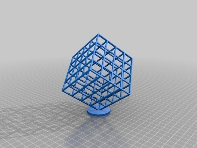
                This summer I spent the past few months acquiring a 3D resin printer and learning how to use it for this eventual internship with the intent of getting some of the learning bumps out of the way before the actual start of the internship. The picture below is an image of one of my first 3D prints that failed. It was intended to be a 3D lattice cube but failed to stick to the build plate and fell into the vat of resin and cured against the bottom FEP film that separates the resin from the UV light that cures and builds the model.


This is an image of the failed Lattice Cube test model

This is a rendering of what the Lattice Cube test model was intended to look like.

I also tried my hand initially at photogrammetry before failing spectacularly using bad technique, bad lighting and free software. The image below shows the image profile of my first attempt. The idea was to capture the golden warrior figure in 3D and soon found out that the photogrammetric program needs photos from points that require actually moving around the object instead of just turning it as the background is in part what allows the program to recognize the change in position between the photos and therefore create an accurate 3D model. My initial creation rendered the background into 3D based off of what the images showed but the golden model ended up being a blob with no real definition.

The background in the image would distract the program and cause the golden warrior pictures to overlay on each other creating the 'blob' while the rest of the scene rendered into 3D

                I learned soon, however, that the program can be fooled into thinking I was moving around the object by placing it in a photo box on a lazy Susan. This method allows the background to be indescribable to the program and the only point of reference to create the 3D model is the model/artifact itself.  This method also allows for even and easy lighting as well as preventing the need to constantly move the camera into 40 to 50 new points around the model.


The photo box and lazy Susan creates a scene free from noise and distractions allowing the program to only recognize the model in the image and therefore be tricked when it comes to movement around the model.

It is my goal in the coming days to try this method out using my newly acquired photo box and lazy Susan and learn to input these into Metashape while also printing the test models from FPAN. My initial work in the coming week for Metashape will be small detail-oriented models that I have lying around the house while I await the coming artifacts next week.


Friday, August 28, 2020

FPAN 3D modelling and printing Internship - Week 1

My name is Trevor Colaneri and I am in the start of my second year in the Public History MA program at UCF as well as being a current teacher for OCPS as 6th grade World History and 7th grade Civics teacher.

My internship with the East Central FPAN office focuses on the comparison of the two most popular 3D printing methods being FDM plastic printing and SLA resin printing. The project consists of the creation of five 3D models using low-cost photogrammetry as well as their subsequent printing and preparation. I will print and prepare those artifacts printed on the resin printer while Emily Dietrich will print those same models on FPAN’s FDM printer where then both sets of prints can be compared on their replication abilities. The culmination of this project with FPAN will be the presentation of a co-authored paper on our findings at the Society for Historical Archaeology 2021 conference.

FDM printing has, for the past few years, been the most common, cheapest, and readily available 3D printing method that is available recreationally and commercially. However, in the past 2-3 years resin printers have started to become more widely available recreationally while also becoming more economically feasible. Resin SLA printers excel in small objects with a lot of detail but generally struggle with larger objects for a variety of reason with the most important being the print bed’s size. FDM printers generally counter by being able to print much larger objects with the struggle of small detailed oriented objects.

The goal of this internship is to compare these two affordable printing methods using a small collection of artifacts and compare the results to evaluate any notable differences between the two as well as the printing process associated with each.

The skills I hope to gain from the internship would be the creation of 3D models using photogrammetry as well as developing and continuing my practice and understanding of 3D printing. These skills directly relate to my thesis and will assist me greatly in learning the process of photogrammetry, metashape, and printing which will save me time later on during the actual project portion for my thesis.

Wednesday, February 19, 2020

Week 1 VLP


This week I started my involvement with the VLP project by watching the first three episodes of Ken Burn’s Vietnam and reading the first two chapters of The Things They Carried by Tim O’Brien as well as looking at storyboarding guides to get a fresh idea on how to best craft a story surrounding a particular Veteran. I enjoyed how both the documentary by Burn and the book by O’Brien tackled this question of shaping a narrative in different ways. Ken Burn’s series follows the lives of certain veterans in relation to major political and cultural events. Whilst talking about the events that largely predated the Vietnam war, the use of first person testimonies always would ground the narrative into the events that would come, or would result immediately after a decision. The documentary also takes a very dark and emotional vibe in order to truly make the viewer feel a sympathetic link to these events suck as using the thumping sound of a helicopter closing in, or the tense static sounds of a radio break to enhance a story about communication, even to the sound of gunshots as Diem and his brother were assassinated in a coup. It wasn’t just audio that lent itself to these veterans stories but chilling images and videos, that could either set the scene for a veterans story or lend itself to the brutality they witnessed. While I am not advocated for such a shock and awe narrative, the expert use of sound and images are witnessed to such a resounding impact and help create an effective narrative.
              The Things They Carried  based off my initial reading, seems to take a singular and down to earth view of a few characters, although still humane and emotional. The story follows the Vietnam war through the eyes of a particular group of soldiers with reprieves that seem to be about the meta of constructing this narrative. The opening chapter makes it a theme to always mention the things each solider carried; the physical weight of their equipment, the emotional weight of loved ones or lost soldiers, the mental weight of what boring, arduous, and at random times dangerous work, to even the moral weight of responsibility serving as the explanation of their presence in Vietnam. This constant reminder of all thus weight allows the reader to see this explanation for the reactions of certain individuals and humanize them more.
              While I do not know who the veterans are yet for our story crafting, some of the threads I liked where the way to also have the veteran humanized, either through visual or auditory cues, to just making them more of the center point. Another interesting thread is how the veteran can serve as the center of the story or can be the human, emotional centerpiece that connects the larger political and cultural narrative. For a project that encompasses one veteran and their individual story unknown, Ill have to wait and see what group I am in and what type of story will serve as the basis.